Building a Tricorder with an ESP32
Building a Tricorder with an ESP32
Why?
There are three main reasons why I started this project:
- It is part of a course for university
- I recently joined a Star Trek themed association which does a lot of projects with teenagers. A working tricorder would be a cool asset
- It’s awesome
What should it do?
The first task is to think of some possible functions. It should not just be a blinking props. The first things that come to my mind are:
- Temperature and humidity. This should be fairly easy using a DHT22.
- Measure distances. Also pretty easy using an ultrasonic sensor.
- Display Information. Of course I am going to need a display. The bigger the better, but price is a concern.
- An NFC Scanner. Hiding NFC tags on objects, making them scannable could be great for missions
- A sensor for air quality, maybe measure different gasses
- LEDs blinking to show progress/status
- Buzzer for the classic sound effects
Part shopping
After some (read: a lot) of searching, I settled on my parts. Temperature and Humidity will be measured using a DHT22 sensor. For the distance measurement I went for the classic HC-SR04 that I already have. To display information I went with an 1.3 inch OLED screen. For the NFC scanner I bought a PN532, and for the air quality measurements I went for the MQ135 sensor.
For the compass I ordered an GY-271 (or so I thought). The first that arrived was dead on arrival, and I had to search for another one. There are very similar versions of this chip, and I wanted to get the correct one.
Starting small
Now, since I need to integrate all those sensors, it is time to approach the programming in a more structured approach. So far, whenever I programmed an Arduin/ESP I just added all my code to the main .ino file. This would lead to a huge mess with all those sensors, so I figured I should divide my code into different files and classes. I need to note, that my main exposure to C++ was a short programming course in university a few years ago. Yikes. The first part in question was the DHT22. I have used this part multiple times in different projects. Also, it is a quite simple and well documented sensor, so no problems here. Now I could print the temperature and humidity to the serial monitor. Well, thats not cool, so the next part I will have to add is the screen.
There is no way I will/can do this without external code, so I went searching. I settled on u8g2 by olikraus. The setup had me enduring some pain, as I needed to figure out which model correlated to my display. I ended up using the U8G2_SH1106_128X64_NONAME_F_SW_I2C, which seems to work fine. However, I had a lot of problems trying to display text in multiple lines. If there is a function included for displaying multiple lines of text, please tell me.
My solution was to write a function which takes an array of strings and draws each string on a separate line. Not perfect, but it works okay.
The part I (intentionally) ignored
At this point, I could no longer skip the part I neglected so far. Admittedly, this has always caused me pain. The power supply. It doesn’t matter if I build a LED lamp or something else, this always bothers me. My first ‘good enough’ solution was to just include a powerbank. However, most automatically shut of when there is low power draw, which is the case with an ESP. I even found an old powerbank which does not have such a feature, but It could power the device for half an hours before dying. Thats a pretty weak powerbank. Also, a powerbank is kinda bulky. When searching for a solution, I stumbled uppon the batter shield for 18650 batteries. The shield provides 5V and 3.3V, which is great for my usecase. It also includes a charing port for the battery. So I went towards ebay and looked for some batteries. AND HOLY SHIT, THERE ARE A LOT OF FAKE VALUES. For example, “Ultrafire battery 9800mAh, 3.7V”. Tha looks like a lot of capacity for such a small battery. On Ultrafire’s store, there is no mention of such a battery. Also, there are many articles/posts along with common sense that tell me to avoid this at all costs. I end up settling for some old camera batteries, which seem to work great so far.
Selecting a sensor
If I want to integrate multiple sensors, I will also need a way to select the currently active sensor. For this, I use a potentiometer. The reported value is clamped to a value corresponding to a sensor id. However, the selection process is pretty slow right now. To speed things up, I use the two cores of the esp32. I spawn a second thread, which keeps polling the potentiometer. The currently selected module is stored in a static variable. Now I can check in my loops if a different sensor was selected and I need to break out of the current loop. This makes the process a lot more responsive. There are still some tasks that are not interruptable, but this is fine with me.
Organizing my programm
So far, whenever I have written something for an Arduino I simply put everything in the main .ino file. Since this project would be more complex than any other I have done so far, I needed to adjust my structure.
I settled for a src folder, which contains a .h and .cpp file for all “modules”. I have to admit, my experience with C++ in general is pretty limited, so this made the entire progress much harder than it needed to be.
For now, I have my main class, which contains the Arduino setup() and loop() method. During setup, an object from all other classes is instantiated (if necessary). I tried to make classes static, so I do not need to keep an object.
Since I heavily relied on the existing libraries for the sensors I had some problems adjusting my code to properly work in some instances.
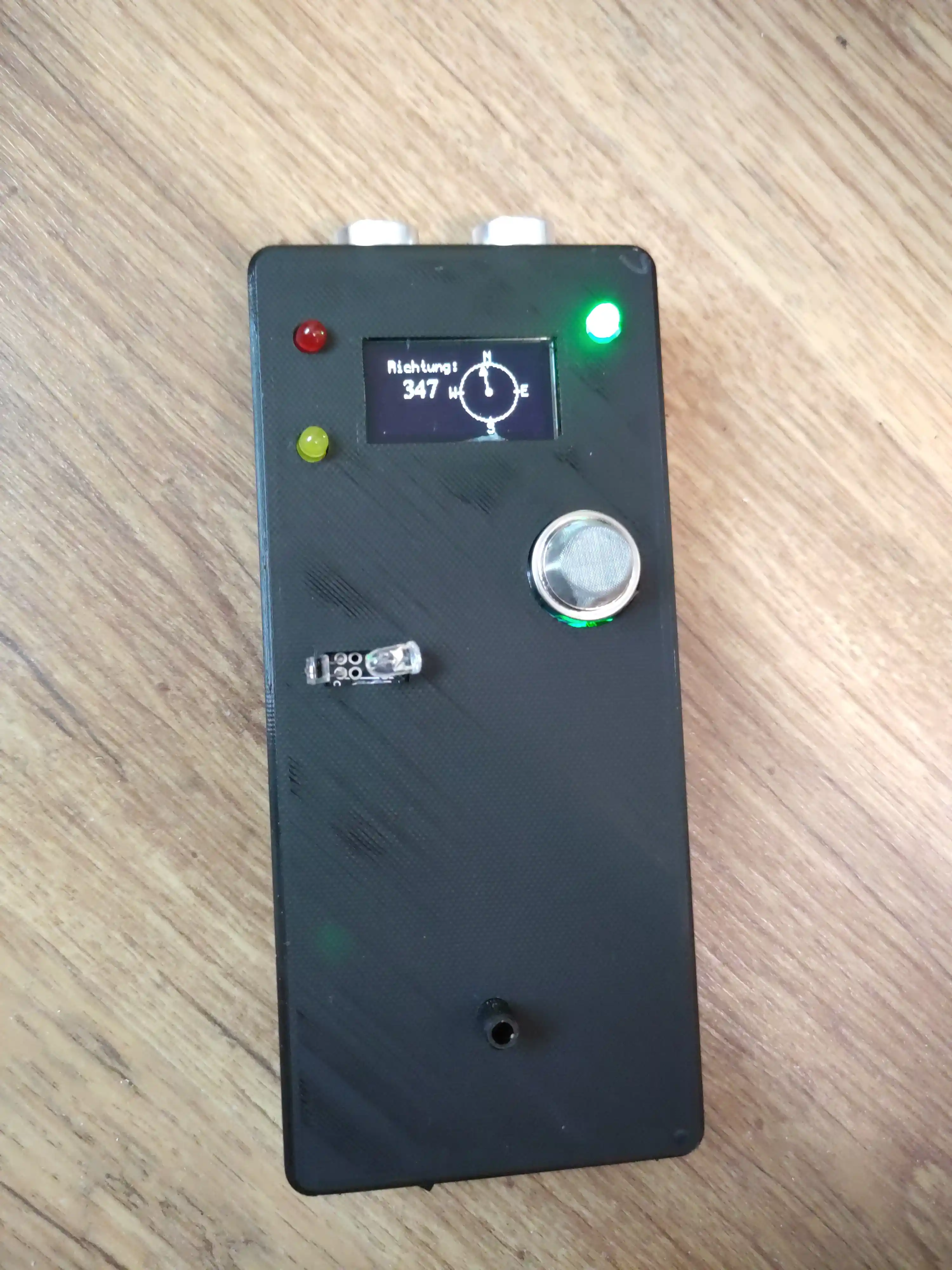
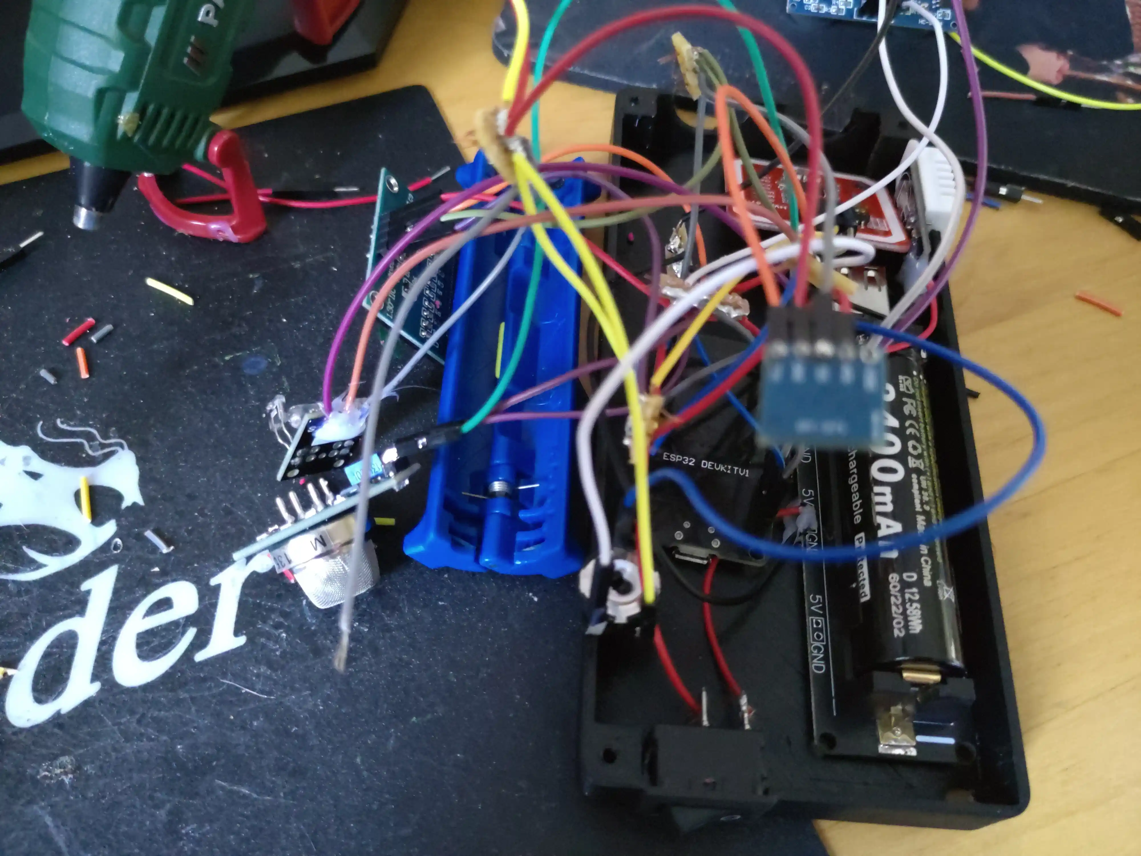
Building the hardware
My girlfriend designed me a case in which I could fit all the sensors and the ESP32. However, after soldering everything together: I noticed something. I should have thought more about the necessary cable lengths and sensor positions. The case could not be closed because it was just a big knot of cables. So my girlffriend saved me here by resoldering everything.
Current problems
After finishing my first prototype, there are some problems that I will need to address in the future.
- The soldering is still not great. In the future, I want to design a pcb for the circuit in order to simplify this.
- The heartbeat sensor does not work properly under the given conditions. There is a lot of movement since the tricorder is a handheld device. There is also a lot of varying light. This leads to very inaccurate measurements
- The air quality sensor needs to warm up for a long time and there are calibration problems. The warm up phase by itself is not too bad. However, there seem to be calibration problems, leading to bad readings in some scenarios. I will need to investigate/research this further
- The compass seems to be disorientated by the electromagnetic field of the cables. For this, I need to find a way to isolate the sensor from the other electronics.
- I was not able to make the piezo buzzers sound like a tricorder. The resulting sounds made me skip sound completely for now
Conclusion
Considering that this prototype was built in a few weeks, I am very proud of the result. It is a working device, which can measure different real world values. Not everything works good, but that can be fixed.